How to Control a Stepper Motor With a Driver
Learn how to control a stepper motor with a driver board, from wiring and current limits to step and direction signals.

On this page
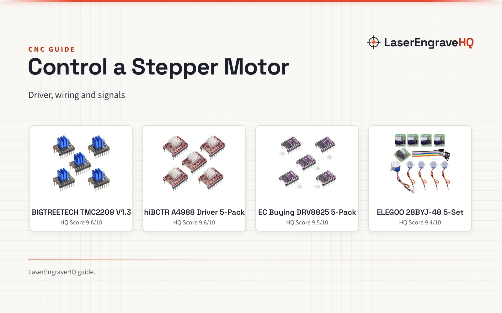
Top picks at a glance
As an Amazon Associate I earn from qualifying purchases.
- 1
 BIGTREETECH TMC2209 V1.3 Stepper Motor Driver9.6/10View on Amazon
- 2
 hiBCTR 5-Pack A4988 Stepper Motor Driver Module9.6/10View on Amazon
- 3
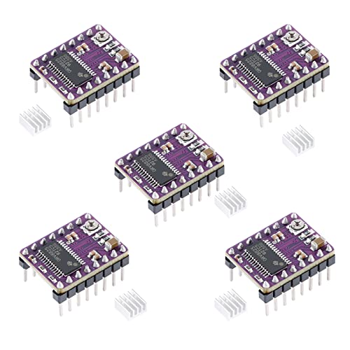 EC Buying DRV8825 Stepper Driver9.5/10View on Amazon
- 4
 ELEGOO 5 Sets 28BYJ-48 ULN2003 5V Stepper Motor9.4/10View on Amazon
A stepper motor only moves when a driver tells its coils when to energise, and that driver sits between the controller and the motor. Learning how to control a stepper motor means wiring the driver to both, setting the current limit for the motor where the driver has one, and sending control signals from the controller. This guide walks through each part of that chain, then matches driver boards to the job they handle.
LaserEngraveHQ earns a commission from purchases made through these links, at no extra cost to you. Read our affiliate disclosure.
Driver ratings differ from listing to listing, so match the driver to the motor and the control board.
BIGTREETECH TMC2209 V1.3 Stepper Motor Driver
A TMC2209 stepstick driver with StealthChop2 silent operation, UART and STEP/DIR modes, StallGuard4 sensorless homing and a heatsink.
Pros
- StealthChop2 silent operation for two-phase stepper motors
- Continuous current up to 2.0A, peak of 2.8A, 4.75V to 28V
- Step modes from 1 to 1/256, UART and STEP/DIR
- StallGuard4 sensorless homing detects the end of an axis stroke
Cons
- No warranty term is stated in the listing
- Firmware must be changed for the mode you use
- Works with the listed control boards; other boards are not named
- Heatsink is included but no thermal rating is stated
hiBCTR 5-Pack A4988 Stepper Motor Driver Module
An A4988 driver module with five microstepping resolutions, an adjustable current potentiometer, thermal protection and a heatsink.
Pros
- Five step resolutions from full-step to sixteenth-step
- Onboard potentiometer sets the maximum current output
- Thermal shutdown, under-voltage lockout, crossover-current protection
- Intelligent chopping selects the optimal current decay mode
Cons
- No warranty term is stated in the listing
- Continuous current up to ±1.2A per phase, lower than the DRV8825 listing
- Microstepping stops at sixteenth-step; no finer mode is stated
- No step rate or speed rating is stated
EC Buying DRV8825 Stepper Driver
A DRV8825 driver module on a 4-layer PCB with a 45 V and ±2.5A output, step modes down to 1/32 and a heatsink.
Pros
- Maximum output capacity of 45 V and ±2.5A
- Step modes from full step down to 1/32
- 4-layer PCB board with better heat dissipation
- Same 1.5cm x 2cm size as the A4988
Cons
- No warranty term is stated in the listing
- No thermal shutdown or protection circuits are stated
- Heatsink is included but no current rating with it fitted is stated
- No microstepping finer than 1/32 is stated
ELEGOO 5 Sets 28BYJ-48 ULN2003 5V Stepper Motor
Five matched 28BYJ-48 geared stepper motors with ULN2003 driver boards, jumper wires and coil-sequence LEDs for small low-speed projects.
Pros
- Five complete motor and driver sets for prototypes and spares
- ULN2003 boards with IN1-IN4 inputs and four onboard LEDs
- 5 V unipolar geared motors with a 1:64 reduction
- Includes 10 female-to-male jumper wires for direct docking
Cons
- 5 V geared motors suit light loads only
- Low-speed movement only; no high-speed rating is stated
- No warranty term is stated in the listing
- Geared design with a 1:64 reduction limits shaft speed
How to control a stepper motor
A controller sends step and direction signals, a driver turns those signals into coil current, and the motor moves one step per pulse in full-step mode, or one microstep per pulse in a finer step mode. Pick the driver first, then wire it, set the current limit, choose a step mode and send signals.
Step 1: Wire the driver between the controller and the motor
Power the motor through the driver board, not through the controller. On a ULN2003 board, connect the control signals to IN1-IN4, and the four onboard LEDs show the active coil sequence while you set up. Stepstick drivers plug into the control board; the ULN2003 board wires to the controller with jumper wires. Connect the controller ground and the motor supply ground together, and check the motor plug and the IN1-IN4 sequence before the first move.
Step 2: Set the current limit and the step mode
Set the maximum current before the motor runs under load. The A4988 sets its maximum current with the onboard potentiometer, the DRV8825 lists a maximum output of 45 V and ±2.5A, and the TMC2209 lists a continuous current up to 2.0A with a peak of 2.8A. Keep the continuous rating in mind, since the peak figure is not a running current. Step mode decides how fine each move is: the TMC2209 runs from 1 to 1/256 step modes, the DRV8825 runs in full step and 1/2, 1/4, 1/8, 1/16 and 1/32 step mode, and the A4988 offers five selectable step resolutions from full-step to sixteenth-step. The A4988 listing states that its five selectable step resolutions allow for smoother, quieter operation and increased positioning accuracy.
Step 3: Send step and direction signals
With wiring and current set, the controller sends step and direction signals and the driver chops the coil current to follow them. The TMC2209 supports UART and STEP/DIR mode, and the listing states that you need to modify the firmware for the mode you use. Its StallGuard4 technology detects changes in motor current and can detect the end of an axis stroke, which the listing states can produce printers without limit switches. If the shaft buzzes or vibrates, reduce the speed and check the wiring sequence. For a machine away from a computer, read the offline controller vs PC control guide.
The driver boards and motors
The driver is the part that turns controller signals into coil current, so the board you pick decides the current, the step modes and the wiring for the job.
Common mistakes to avoid
- Powering the motor from the controller.
- Leaving the grounds unconnected.
- Skipping the check of the plug and the IN1-IN4 sequence.
- Running at a speed that makes the shaft buzz.
- Treating peak current as running current: the TMC2209 lists 2.0A continuous and 2.8A peak.
How to control a stepper motor: the short version
- Wire the driver between the controller and the motor.
- Set the current limit, then pick a step mode.
- Send step and direction signals from the controller.
- Watch the coil sequence, and reduce speed if the shaft buzzes.
FAQ: lasers and CNC
Can I control a stepper motor without a driver board?
No. The driver board sits between the controller and the motor and powers the coils in sequence, turning the controller’s step and direction signals into coil current.
What does microstepping change?
Microstepping splits each full step into smaller moves. The A4988 listing states that its five selectable step resolutions allow for smoother, quieter operation and increased positioning accuracy. The TMC2209 lists step modes from 1 to 1/256, and the DRV8825 lists modes down to 1/32 step.
Why does my stepper motor buzz instead of turning?
The ELEGOO listing gives a set of checks: use a regulated 5 V supply, connect controller and motor-supply grounds together, verify the motor plug and IN1-IN4 sequence, and reduce speed if the shaft buzzes or vibrates.
Do I need limit switches with sensorless homing?
Not always. The TMC2209 listing states that StallGuard4 detects changes in motor current and can detect the end of an axis stroke, which can produce printers without limit switches. The board still needs its firmware set for the mode you use.
Which driver board fits a small low-speed project?
The ELEGOO sets (on Amazon) suit clocks, gauges, rotating displays, feeder gates, vents and small robot mechanisms. Each 28BYJ-48 uses a 5-wire, 4-phase design with a 1:64 reduction for controlled low-speed movement in light-load positioning projects.
Related: the stepper motor vs servo motor guide, the closed loop vs open loop stepper guide and the stepper motor size chart.