How to Make a Material Calibration Grid in LightBurn: A Practical Setup Guide
A practical step-by-step guide explaining how to make a material calibration grid in LightBurn, set speed and power axes, frame scrap stock safely, and save presets.

On this page
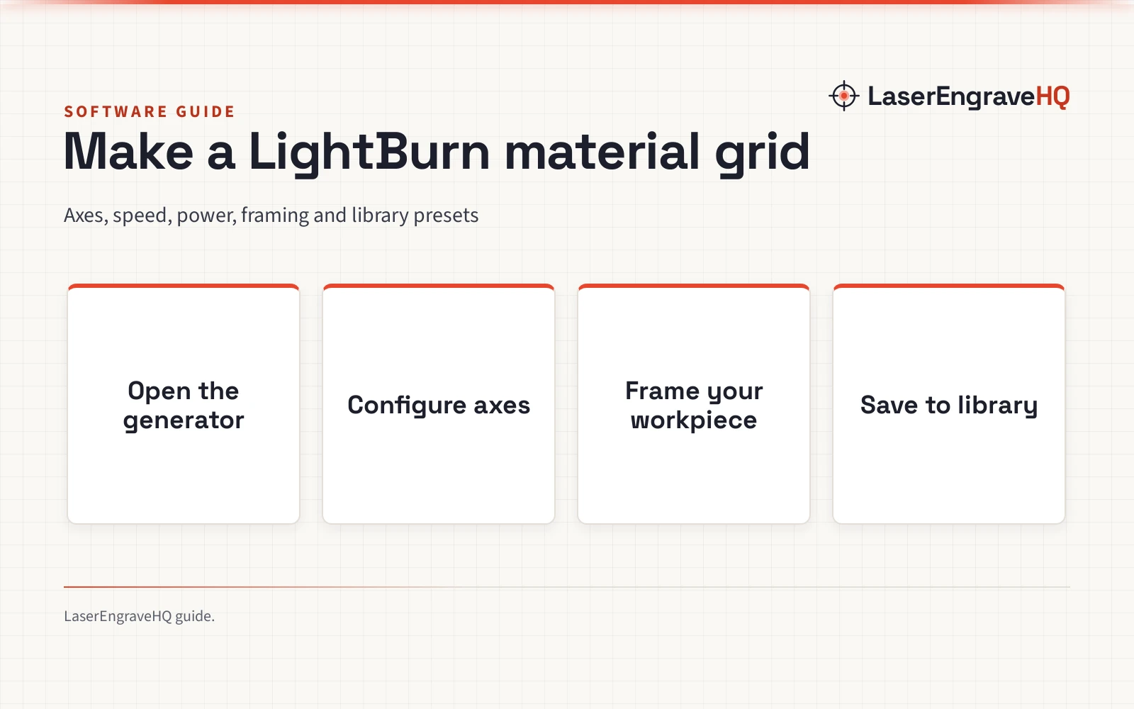
Learning how to make a material calibration grid in LightBurn comes down to using the built-in generator under the Laser Tools menu: select the material calibration generator, define your speed and power ranges across both axes, choose row and column counts, frame your scrap workpiece, and run the job to identify the cleanest burn settings. Generating a LightBurn calibration grid directly inside the software eliminates guesswork, prevents wasted project blanks, and provides a permanent physical reference for any specific sheet or coating. The sections below walk through each step in order, covering parameter setup, label configuration, framing safety, and library organization.
As an Amazon Associate I earn from qualifying purchases. LaserEngraveHQ earns a commission from purchases made through these links, at no extra cost to you. Read our affiliate disclosure.
Pre-calculated parameter charts found on community forums provide starting points, but differences in machine optical power, focal spot size, ambient humidity, and natural wood grain mean your hardware will behave uniquely. Running a dedicated grid on a scrap cutoff of your exact batch is the reliable way to establish baseline parameters without risking a valuable finished item.
Step 1: Open the Material Generator tool in LightBurn
Modern editions of LightBurn include an integrated calibration tool that builds parameter matrices automatically without requiring manual drawing or layer assignments. To access it, ensure an active laser device profile is selected in LightBurn, then navigate to the top menu bar, open Laser Tools, and choose the material calibration generator. If you are configuring a new machine profile, follow our guide on how to set up LightBurn for a diode laser before running your initial burn. For operators still evaluating software platforms, reading our guide on whether is LightBurn worth it covers how native utilities like this generator streamline workshop production.
When the generator dialogue opens, you will see a preview pane alongside parameter fields for the primary and secondary axes. The software builds a grid of sample squares where each square executes a unified combination of operating values. In earlier editions of laser control software, operators had to draw individual vector rectangles and manually assign distinct cut layers to each shape. The built-in generator automates this process into a unified pattern, allowing you to preview the entire layout before burning.
Step 2: Configure the speed and power calibration axes
The core of any parameter matrix is establishing the primary working variables: travel speed and laser power. By standard convention, operators map travel speed along the horizontal axis and laser power along the vertical axis, though LightBurn allows you to reverse them if preferred. Set your minimum speed fast enough to prevent excessive heat buildup and severe scorching, and set your maximum speed within the mechanical limits of your motion system to avoid vibration or lost steps. Consult our baseline laser engraver speed and power settings chart to get a practical overview of typical operating ranges across different laser sources.
For the power axis, configure the minimum power setting slightly above your laser source firing threshold so the beam reliably strikes the target material on every pass. Set the maximum power value near the upper operating limit for your module, reserving maximum output for deep cutting or dense hardwoods. Choose row and column counts that produce clear gradations without overcrowding the pattern. Using equal steps across both axes ensures that adjacent patches demonstrate distinct visual contrast in depth, darkness, and edge crispness.
Step 3: Set grid dimensions and material labels
After defining the operating ranges, adjust the physical size of individual sample patches and the overall layout. Sizing each patch sufficiently wide allows you to evaluate surface texture, shading uniformity, and surface scorch clearly. Leave a small border gap between adjoining patches so that heat and localized scorching from high-power cells do not bleed across the boundary lines into lower-power neighbors. This separation keeps each square isolated and readable.
Enable the text label option inside the generator so that LightBurn automatically engraves parameter readouts along the top and side borders of the grid. These labels display the corresponding speed and power figures next to each row and column, creating an indexed reference card on the finished workpiece. Make sure the text layer uses an engraving mode fast enough to mark legibly without burning through thin stock. You can also specify an optional cutout perimeter around the finished grid if you want to detach the completed swatch card from your larger stock sheet for storage.
Step 4: Frame and run the calibration pattern on scrap stock
Never run a calibration pattern on valuable project blanks or finished goods. Secure a flat scrap offcut from the exact sheet, board, or coating batch you intend to engrave, as density and resin content vary even between boards of the same species. Place the scrap workpiece flat on your worktable or honeycomb bed, focus your laser optics precisely to the material surface, and use the LightBurn framing feature to verify that the entire matrix fits within the scrap boundary before firing.
Workshop safety and fume management must be active throughout the job. Never attempt to mark or cut prohibited materials such as PVC, vinyl, PVC-based faux leather, polycarbonate, or ABS, because these polymers produce corrosive acidic gas and dangerous airborne toxins when heated; review our reference on materials you should never laser cut before loading unknown plastics. Activate your exhaust system or extraction unit, keeping workshop air safe in line with standard guidance on whether do laser engravers need ventilation. Wear certified eyewear that matches the optical wavelength of your laser beam as outlined in our laser safety glasses guide. Furthermore, engaging positive airflow helps clear vapor and prevent flare-ups; see our assessment of how air assist makes a difference on a laser engraver. Never leave the machine unattended while the grid executes.
Step 5: Inspect results and save settings to your library
After the burn finishes, allow the workpiece to cool, clear away residual smoke, and inspect the matrix under good lighting. For engraving projects, look for the patch that delivers rich contrast and crisp text borders without excessive charring or deep surface trenching. For wood projects where smoke residue can smudge details, applying the techniques in our guide on how to prevent burn marks when laser cutting wood helps preserve surface contrast. For cutting applications, check the underside of the workpiece to identify the fastest travel speed that achieves a complete through-cut at a given power level without causing excessive charring or wide kerf.
After identifying the best combination, save those exact values into the LightBurn Material Library. Open the library window, select your laser machine, create a material entry named after your specific stock, and store the chosen speed, power, pass count, and air assist settings under appropriate operation labels such as Surface Engrave, Deep Engrave, or Clean Cut. Storing verified settings in your library turns every calibration run into a permanent asset, allowing you to recall precise parameters directly during future production jobs. Discover more workflow tips in our central laser software section.
Common mistakes to avoid
- Using pre-calculated parameter tables from other makers without verifying them on your specific machine and material batch.
- Forgetting to frame the pattern on the scrap cutoff, resulting in the laser striking hold-down clamps or burning off the material edge.
- Omitting text labels on the grid axes, leaving an unindexed collection of burned squares with no record of which setting created each patch.
- Attempting to calibrate focus and laser settings simultaneously rather than establishing precise optical focus prior to running the matrix.
- Failing to record air assist status during calibration, leading to inconsistent results during subsequent production runs.
- Failing to save verified parameters directly to the LightBurn Material Library for future recall on customer projects.
How to make a material calibration grid in LightBurn: the short version
- Open the Laser Tools menu in LightBurn and launch the material grid generator.
- Set the horizontal axis to travel speed and the vertical axis to laser power.
- Define upper and lower operating ranges that match your laser module capabilities.
- Enable axis text labels and add border spacing between individual sample squares.
- Focus your optics and frame the full pattern boundaries on a scrap cutoff of your project material.
- Turn on workshop ventilation, set appropriate air assist, and wear certified eye protection, then run the job.
- Examine the finished swatches and save the winning speed and power values into your Material Library.
Following this repeatable process takes only a brief calibration run on scrap stock, yet it guarantees that production jobs start with proven parameters suited to your specific laser and workpiece.
FAQ: lasers and CNC
Where is the material grid generator located in LightBurn?
The material grid generator is located in the top menu under Laser Tools, labeled Material Generator. It is available when an active laser device profile is selected in LightBurn. If the option appears grayed out, verify that your machine profile is selected in the laser control window and that LightBurn is not currently executing an active job.
Should speed or power be placed on the horizontal axis?
Placing travel speed on the horizontal axis and laser power on the vertical axis is standard workshop convention, but the choice is flexible. The crucial factor is enabling text labels so the generated swatch card clearly displays which parameter controls each axis. Consistency across all your sample swatches makes visual comparison straightforward when choosing parameters later.
What is the difference between fill and line mode on a calibration grid?
Fill mode raster-engraves solid patches by sweeping back and forth across each square, making it ideal for determining engraving darkness, raster depth, and surface finish. Line mode traces only the vector perimeter of each square, making it suitable for evaluating vector scoring, cutting depth, and kerf width. Choose the mode that corresponds to the specific operation you plan to run on your finished product, as detailed in our guide on laser engraver file types.
Why do text labels fail to burn on the calibration matrix?
If text labels do not appear on your completed grid, verify that the text layer within the generator dialog is toggled to output. In addition, ensure that the power setting assigned to the label layer is high enough to mark your stock visibly while maintaining a travel speed that prevents burning through thin material.
How do I save the best settings from my calibration grid?
After identifying the cleanest swatch on your sample board, open the Material Library tab in LightBurn, choose or create a material category matching your stock, and create a new preset. Enter the speed and power values from that winning swatch, specify whether air assist was enabled, and assign a descriptive name such as Dark Engrave or Through Cut. Once saved, you can apply those exact settings to any future design layer immediately.
Related: our starter guide on laser engraving software for beginners, our comparison of open frame vs enclosed laser engraver models, and our guide to the best plywood for laser cutting.