How to Set Up a Spoilboard on a CNC: A Step-by-Step Setup Guide
A practical step-by-step guide on how to set up a spoilboard on a CNC router, covering material choice, bed mounting, flycutter surfacing, and spindle tramming.

On this page
Top picks at a glance
As an Amazon Associate I earn from qualifying purchases.
- 1
 CNC Spoilboard Surfacing Router Bit9.6/10View on Amazon
- 2
 CNC Spoilboard Surfacing Router Bit9.6/10View on Amazon
- 3
 VEVOR Linear Rail9.7/10View on Amazon
- 4
 CNC Spoilboard Surfacing Router BitView on Amazon
- 5
 Slab Flattening Router Bit 1/4" ShankView on Amazon
- 6
 CNC Spoilboard Surfacing Router Bit 1/2" ShankView on Amazon
- 7
 6Pcs CNC Router Bits SetView on Amazon
- 8
 CNC MDF Spoilboard for LUNYEE 3018 CNC Router MachineView on Amazon
- 9
 CNC Spoilboard Surfacing Router Bit 1/4 Inch ShankView on Amazon
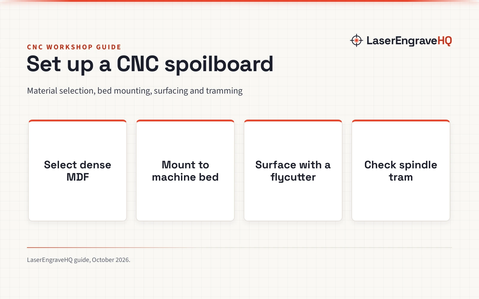
How to set up a spoilboard on a CNC involves mounting a sacrificial board to the machine bed, fastening it below the reach of your cutters, and surfacing the top face completely flat with a wide flycutter so it sits perpendicular to the spindle axis and parallel to the machine’s travel plane. This sacrificial base protects your aluminum bed from through-cuts, provides a uniform workholding foundation, and delivers consistent cutting depth across your entire work area. The sections below explain how to select the right material, fasten the board properly, configure your surfacing toolpath, and align your machine for clean woodworking results.
Other machines to compare
 CNC Spoilboard Surfacing Router BitCheck price on Amazon
 Slab Flattening Router Bit 1/4" ShankCheck price on Amazon
 CNC Spoilboard Surfacing Router Bit 1/2" ShankCheck price on Amazon
 6Pcs CNC Router Bits SetCheck price on Amazon
 CNC MDF Spoilboard for LUNYEE 3018 CNC Router MachineCheck price on Amazon
 CNC Spoilboard Surfacing Router Bit 1/4 Inch ShankCheck price on Amazon
LaserEngraveHQ earns a commission from purchases made through these links, at no extra cost to you. Read our affiliate disclosure.
A factory aluminum bed is rarely level relative to the spindle travel. Fastening an MDF board directly to the machine and cutting away high spots with a surfacing pass creates a reference plane that matches the motion of your specific router.
Step 1: Select the right spoilboard material
Medium-density fibreboard (MDF) serves as the standard spoilboard material across desktop and production CNC routers. MDF offers uniform density, lacks knots or grain direction, and cuts cleanly without dulling carbide tooling prematurely. Its porous composition also supports vacuum hold-down and provides a stable base for hold-down clamps.
Pre-cut panels provide a reliable starting point. Genmitsu specifies dense MDF spoilboards measuring 12 mm thick for its desktop routers, including replacement panels measuring 300 x 200 x 12 mm and 360 x 300 x 12 mm. For larger platforms, AnoleX lists an MDF wasteboard measuring 500 x 400 x 12 mm weighing 4.59 pounds. Standard MDF absorbs ambient moisture over time, so storing panels flat in your workspace stabilizes them before installation. To explore dedicated replacement panels, consult our guide to the best CNC spoilboard options.
Step 2: Size the board and align the mounting layout
The spoilboard should span the accessible cutting area of your machine without interfering with frame uprights, linear rails, or limit switches. When retrofitting a compact benchtop machine, align the board dimensions to the underlying work table. For example, Lunyee specifies an MDF spoilboard measuring 300 x 180 x 12 mm engineered for its 3018 series routers, incorporating 24 holes with a maximum distance between holes of less than 54 mm.
Matching hole spacing to your machine bed prevents flex during heavy cutting. If you cut your own blank from sheet stock, mark hole locations that align with the bed slots. Pre-drilling through-holes and counterboring recesses allows the screw heads to drop below the cutting plane. On compact machines such as the desktop units featured in our desktop CNC router guide, maintaining clear access to the perimeter allows hold-down clamps to secure stock without obstructing gantry travel.
Step 3: Fasten the spoilboard firmly to the machine bed
Rigid workholding starts beneath the workpiece. Any vibration or upward lift between the spoilboard and the underlying aluminum table transfers directly into your cuts, causing chatter marks or dimensional errors. Most desktop machines feature an aluminum extrusion table with mounting tracks. Genmitsu lists an aluminum profile base with 4 T-slots on both sides to accept standard clamping hardware.
Fasten the board using corrosion-resistant hardware. Genmitsu specifies M6 screws (6 mm) to mount its 3020 board using 4 screws through pre-drilled holes. Counterboring each hole is critical so screw heads sit beneath the cutting plane. AnoleX specifies that its MDF spoilboard surface sits about 1.5 mm higher than the fixing screw heads. This 1.5 mm clearance margin provides space for light initial skimming passes without contacting the fasteners. Tighten screws progressively from the center outward to seat the fiberboard flat against the metal bed. For stock clamping techniques once the board is mounted, read our overview of the best CNC hold down clamps.
Step 4: Choose a dedicated surfacing bit and set your toolpath
Flattening a spoilboard requires a wide flycutter or surfacing router bit rather than a standard end mill. Surfacing bits feature horizontal cutting edges that plane away material across overlapping swaths. Replaceable carbide insert cutters are an economical choice for fiberboard, as rotating dull inserts restores a sharp edge without replacing the entire tool.
Match the tool shank to your router collet. For machines with a 1/4-inch collet, BINSTAK lists a 2-wing carbide insert surfacing bit featuring a 1/4-inch shank, a 1-1/4-inch cutting diameter, and 12 mm square carbide inserts with a 2.2 mm blade thickness. Akylin lists a 2+2 wing cutter with a 1/4-inch shank, a 1-1/2-inch cutting diameter, and indexable carbide inserts measuring 12 mm by 12 mm by 1.5 mm, designed for 90-degree corners. For routers with a 1/2-inch collet, Trvoxviq specifies a 2+2 wing cutter with a 1/2-inch shank and a 2-inch cutting diameter that includes 10 replacement inserts. Trvoxviq also offers a 1/4-inch shank model with a 1-1/4-inch cutting diameter and a total length of 1.81 inches (46 mm) requiring at least 20 mm of collet clamping depth.
In your software, generate a raster toolpath running parallel to the longest machine axis. Specify a partial stepover so consecutive passes overlap generously. For tool geometry details, see our guide to the best surfacing router bit designs.
Step 5: Execute the surfacing pass and manage airborne dust
Before cutting, manually jog the spindle across the spoilboard to find the highest point on the material. Lower your tool to touch off on this high spot and establish your Z-axis work zero, ensuring the cutter never plunges too deep on its initial approach.
Take light, shallow cleanup passes to prevent spindle bogging and maintain tool balance. Run your spindle at a moderate speed within the maker’s recommended operating range, and maintain a steady feed rate to prevent heat buildup. Surfacing MDF generates substantial airborne dust consisting of fine wood particulates and binder resin. Connect a dust shoe to an active workshop vacuum before starting. Our guide to dust collector shoe for CNC router systems explains how proper extraction keeps linear rails and lead screws clean. Let the machine complete the entire facing cycle without interruption, then inspect the surface for untooled low spots.
Step 6: Inspect alignment, tram the spindle, and maintain the board
Once the surfacing cycle finishes, slide your fingers across the planed surface perpendicular to the toolpath lines. The surface should feel completely smooth. If you detect stepped ridges along the path boundaries, your router spindle is out of tram. Tram refers to the squareness of the spindle centerline relative to the machine table plane.
A wide surfacing cutter magnifies spindle tilt. When the spindle is not perpendicular to the bed, one edge of a 1-1/4-inch or 2-inch cutter cuts deeper than the opposite edge. Tilt across the direction of travel leaves raised ridges between adjacent raster passes, while tilt along the cut path causes the cutter to dish the surface. To eliminate these ridges, adjust the spindle mount tramming screws or insert precision shim stock between the spindle bracket and the Z-axis carriage. Re-run a light finishing pass until the wide bit planes the spoilboard flat without leaving tactile ridges. For feed, speed, and chip load guidelines across different materials, read our primer on CNC feeds and speeds for beginners.
Surfacing also removes any factory markings from the board. Pre-drilled panels from makers like Genmitsu and Lunyee arrive with reference scale grids printed in centimeters for stock alignment. After surfacing, you can carve your own custom reference grid, edge fences, or corner stops aligned precisely to your machine axes. Over time, through-cutting leaves crisscrossing grooves that degrade workholding stability. Plan to resurface your board periodically by running a shallow cleanup skim whenever grooves multiply. Once successive surfacing operations thin the board near its counterbored mounting screws, remove the worn panel and install a fresh MDF blank.
Common mistakes to avoid
- Fastening screws without sufficient counterbore depth, leading to bit collisions with steel hardware.
- Running a wide surfacing cutter at excessive spindle speed beyond its stated rotational limits.
- Attempting heavy, deep surfacing cuts that stall the spindle motor and flex the gantry.
- Ignoring spindle tram, which leaves ridges across the entire spoilboard surface.
- Allowing fine MDF dust to accumulate on lead screws, linear bearings, and stepper electronics.
- Neglecting workshop humidity changes, causing unsealed fiberboard panels to swell unevenly.
How to set up a spoilboard on a CNC: the short version
- Select dense, flat MDF stock sized to fit your machine working envelope.
- Drill and counterbore mounting holes so screw heads sit well below the surface plane.
- Fasten the board firmly to the aluminum bed using T-nuts and low-profile screws.
- Install a dedicated carbide insert surfacing bit and generate a raster facing toolpath.
- Touch off on the highest point of the board and run a light surfacing cleanup pass.
- Verify surface smoothness by checking for ridges, adjusting spindle tram as required.
Following these steps creates an accurate sacrificial platform that protects your machine table and delivers consistent machining depth across every project.
FAQ: lasers and CNC
Why is MDF preferred over plywood for a CNC spoilboard?
MDF features uniform density without internal voids, knots, or directional grain. Plywood contains alternating veneer layers and adhesive voids that can splinter, warp under ambient humidity shifts, and damage fine milling cutters during through-cuts.
How often should a CNC spoilboard be resurfaced?
Resurface the spoilboard whenever through-cutting grooves become deep enough to compromise stock clamping or workpiece flatness. In active workshops, running a shallow skim pass restores a level reference surface as soon as visible wear appears.
Can a standard end mill surface a spoilboard instead of a flycutter?
A standard flat end mill can plane a spoilboard, but its narrow cutting diameter requires many more passes and significantly more machining time. A dedicated surfacing bit with a wider cutting diameter planes the bed efficiently while leaving fewer toolpath transitions.
How deep should a spoilboard surfacing pass cut?
Surfacing cuts should remain as shallow as possible while still removing high spots. Taking light, controlled skimming passes preserves spoilboard thickness, minimizes cutter deflection, and extends the overall usable lifespan of the sacrificial board.
What causes ridges on the spoilboard after a surfacing pass?
Ridges indicate that the spindle centerline is not perpendicular to the machine bed. When the spindle is tilted along either horizontal axis, the wide cutter digs in along that edge. Shimming or adjusting the spindle mount squares the cutter to the table.
What is the difference between a spoilboard and a wasteboard?
The terms spoilboard and wasteboard are used interchangeably in CNC machining. Both describe a sacrificial layer of material mounted to the machine bed to protect the primary table and provide a renewable, surfaced workholding platform.
Related: the CNC router hub, our overview of best desktop CNC for beginners, and how to choose a desktop CNC router. Also see our guide to CNC router bit types.