Why Is My CNC Losing Steps? Causes and Solutions
A step-by-step troubleshooting guide explaining why your CNC router loses steps, covering mechanical binding, belt tension, driver current, wiring, and speed limits.

On this page
Top picks at a glance
As an Amazon Associate I earn from qualifying purchases.
- 1
 SpeTool Carbide Single Flute CNC Router Bits 1/8" Cutting9.7/10View on Amazon
- 2
 VEVOR Linear Rail9.7/10View on Amazon
- 3
 SainSmart Genmitsu 3020-PRO Ultra CNC Router Machine9.7/10View on Amazon
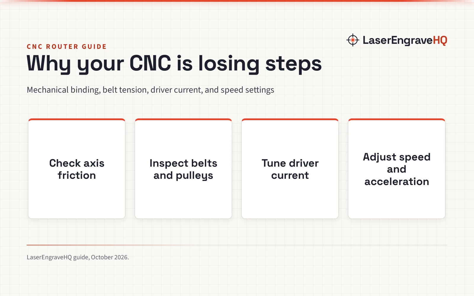
Why is my CNC losing steps usually comes down to mechanical binding along the axes, loose drive belts or slipping motor pulleys, incorrect stepper driver current, driver overheating, electrical noise in the wiring, or commanding cutting speeds and acceleration rates beyond what the stepper motors can deliver. Because standard desktop CNC routers operate without position feedback, the motion controller assumes the machine moved as commanded, meaning any skipped step shifts the remaining toolpath. The guide below walks through each mechanical and electrical cause step by step so you can resolve the issue on your machine.
LaserEngraveHQ earns a commission from purchases made through these links, at no extra cost to you. Read our affiliate disclosure.
Standard desktop CNC routers use open-loop stepper motors. The controller sends step and direction pulses to each motor driver, but the system has no encoders to confirm actual physical position. If physical resistance or an electrical drop causes the motor to skip a step, the machine continues running as if nothing went wrong, leaving a visible positional shift in your workpiece.
Step 1: Check for mechanical binding and axis resistance
Mechanical binding is the most frequent cause of lost steps on desktop cutting machines. When an axis encounters physical resistance, the force required to move the carriage exceeds available motor torque, causing the rotor to slip backward relative to the commanded magnetic field.
Begin by cutting power to the machine and moving each axis by hand across its full travel. The carriage should glide smoothly without catching, tight spots, or grinding sensations. On machines built with aluminum extrusions and V-wheels, eccentric spacers that are adjusted too snugly can pinch the extrusion and create severe friction. Accumulated sawdust, chips, and dried lubricant along lead screws or linear guide rails can also jam linear bearings.
Linear motion hardware is rated for specific payload and velocity thresholds. For example, the FUYU FSK30 linear slide table listing specifies a repeat position accuracy of 0.02mm, with a maximum rated horizontal speed of 40mm/s and vertical speed of 15mm/s under a maximum horizontal loading of 6.6 pounds and vertical loading of 2.2 pounds. When any axis encounters sawdust buildup, rail misalignment, or excessively tight eccentric spacers, the added frictional load can exceed motor capacity and cause lost steps.
Many entry-level desktop machines, such as those evaluated in our budget CNC router guide, use aluminum extrusions with V-slot wheels or lead screws that require regular cleaning and adjustment to prevent physical binding. If you are setting up a machine for the initial run, our guide on desktop CNC machine for beginners covers proper mechanical alignment.
Step 2: Inspect belt tension and pulley set screws
If your machine moves freely by hand but loses position under load, the drive belt or motor pulley is often responsible. Loose belts allow teeth to jump over pulley grooves during direction reversals, while over-tightened belts place excessive radial loads on motor bearings and lead to stalling.
Belts should feel snug with minimal deflection under light finger pressure, without bowing the drive shafts. Check the belt teeth for signs of fraying, missing rubber, or uneven wear that indicates misalignment between the motor pulley and the idler bearing.
A slipping motor pulley is even more deceitful than a loose belt. Small drive pulleys attach to the stepper motor shaft with miniature set screws, also called grub screws. If a set screw loosens, the motor shaft can spin freely inside the pulley bore under cutting resistance while the pulley stays still. Mark the end of the motor shaft and the pulley face with a permanent marker. If the marks become misaligned after a carving session, the set screw has slipped. Tighten the set screw securely against the flat side of the motor shaft and apply medium-strength threadlocker to keep it anchored.
Step 3: Tune stepper driver current and heat dissipation
Stepper drivers regulate the electrical current delivered to the motor coils. Setting the current too low reduces motor torque and leads to skipped steps under load, while setting it too high causes the driver chip or motor to overheat.
When a driver delivers insufficient current, the magnetic field inside the motor stator is too weak to overcome inertia during rapid direction changes. Conversely, excessive current causes driver chips to reach high temperatures rapidly. Modern stepper drivers incorporate thermal shutdown protection; when temperature thresholds are crossed, the driver cuts power momentarily to cool down, causing immediate and dramatic step loss mid-cut.
Driver specifications show how current ratings dictate operating conditions. For example, the STEPPERONLINE DM542T stepper motor driver listing specifies an operating current range of 1.0 to 4.2A with an input voltage of 20 to 50VDC for Nema 17 and Nema 23 motors, supporting 1/128 microstep resolution. In compact plug-in stepstick formats, the BIGTREETECH TMC2209 driver listing specifies a continuous drive current of 2A and peak current of 2.8A across 4.75V to 28V, providing up to 256 microsteps with dynamic current control to reduce operating heat. Always ensure that driver heatsinks have firm thermal contact and that an active cooling fan directs airflow over the control board.
Step 4: Inspect electrical wiring and power supply stability
Intermittent electrical faults can mimic mechanical binding. Stepper motors rely on alternating electromagnetic pulses through separate motor phase circuits. If a wire connection is loose or momentarily breaks during carriage travel, the motor instantly loses torque and stalls.
Continuous flexing inside drag chains can cause copper strands inside the wire jacket to fracture while the outer insulation remains intact. Inspect terminal block screws on the controller board to ensure every lead is clamped securely. Avoid running motor signal cables directly parallel to AC spindle cords or dust collection hoses, which generate electromagnetic interference and static discharge that can corrupt step signals. In addition, confirm that your power supply maintains stable direct-current voltage under peak cutting loads without voltage sag.
Step 5: Adjust cutting feed rates and acceleration profiles
Stepper motors exhibit an inverse relationship between speed and torque: they produce maximum holding torque at rest, but available torque drops steadily as rotational speed increases. Commanding an axis to move too rapidly during a heavy cut will quickly cause the motor to stall.
Firmware acceleration settings govern how quickly an axis ramps up from standstill to target velocity. If acceleration is configured too aggressively, the inertial load of the gantry will exceed available motor torque during direction changes. Lowering acceleration parameters in your controller firmware often resolves persistent step loss during detailed carvings.
Cutting parameters must also reflect material hardness. Taking excessive depth of cut or driving the tool too rapidly creates cutting forces that overpower the machine. Selecting proper cutters from our guide to the best CNC router bits, reducing cut depth, and making multiple shallow passes keeps cutting forces within the mechanical limits of your stepper motors.
Step 6: Verify controller pulse frequency and signal settings
The motion controller card must generate clean, accurately timed step pulses that match the driver requirements. If the commanded speed and microstep resolution require a pulse rate higher than the controller board can generate or driver optocouplers can process, step pulses will be dropped electronically before reaching the motor coils.
Hardware listings clearly define pulse limits. For example, the CNCTOPBAOS 4 Axis motion control board listing specifies a maximum step-pulse frequency of 100KHz at 24V. When using fine microstep settings, the required step frequency increases substantially for a given travel speed. If your configuration exceeds the rated pulse frequency of the board, the controller cannot generate pulses reliably, leading to silent step loss. Review your controller documentation to confirm that step pulse width and direction setup delays meet the timing specifications of your stepper drivers.
Common mistakes that cause missed steps
- Setting firmware acceleration rates too high for the weight of the gantry.
- Over-tightening drive belts until motor bearings bind.
- Neglecting loose set screws on motor drive pulleys.
- Running stepper driver modules without active fan cooling.
- Taking deep cutting passes in hardwoods instead of multiple shallow passes.
- Routing unshielded motor wiring alongside noisy AC router power cords.
Why is my CNC losing steps: the short version
- Disconnect power and move each axis by hand to identify binding, rail debris, or tight eccentric spacers.
- Inspect drive belts for proper tension and ensure pulley set screws are locked onto shaft flats.
- Tune stepper driver current to match motor ratings and ensure cooling fans circulate air across heatsinks.
- Check wiring harnesses for loose terminal screws, fatigue fractures, and spindle interference.
- Reduce aggressive cutting feed rates and lower firmware acceleration values in your control software.
- Confirm that your controller step pulse frequency and pulse timing match your driver specifications.
Addressing each mechanical and electrical area systematically isolates whether missed steps stem from friction, loose hardware, thermal cutout, or aggressive cutting loads.
FAQ: lasers and CNC
How do I know if my CNC is losing steps or slipping on a pulley?
When a pulley slips on the motor shaft, the motor shaft rotates inside the pulley bore, which you can identify by drawing an alignment line across the shaft end and pulley face with a marker. In contrast, lost steps from motor stalling occur when the motor itself fails to rotate, typically producing a distinct humming or grinding vibration as magnetic poles slip while the rotor stalls in place.
Can a loose wire cause a stepper motor to miss steps?
Yes. Stepper motors rely on alternating electromagnetic pulses through separate motor phase circuits. If a wire connection is loose or momentarily breaks during carriage travel, the motor instantly loses holding torque and stalls.
Why does my CNC router only lose steps during heavy cuts?
As a router bit cuts through material, cutting resistance pushes back against the gantry. If the combined cutting force and inertial load exceed available motor torque, the rotor slips backward relative to the rotating magnetic field, dropping steps during the pass.
Does stepper driver overheating cause missed steps?
Yes. Modern stepper driver modules incorporate thermal protection circuitry. When heat exceeds safe thresholds, the driver temporarily disables motor current to cool down, causing sudden and severe position loss.
What is the difference between open-loop and closed-loop steppers?
Standard open-loop steppers execute step commands without positional verification. Closed-loop stepper systems attach an optical or magnetic encoder to the motor shaft, detecting when an axis lags behind and alerting the system or compensating for position error.
Will increasing power supply voltage help prevent lost steps?
Higher supply voltage allows motor coils to build current more rapidly, which helps maintain torque at higher rotational speeds. However, the voltage must remain within the maximum rating stated on the stepper driver listing to prevent component damage.
Related: the CNC router hub, best desktop CNC for beginners and desktop CNC machine for beginners. Also see our DIY CNC router kit starter guide and our overview of best CNC hold down clamps.